

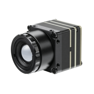
Parametric Quick-Spec & Engineering Decision Matrix
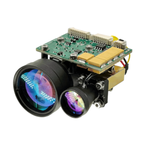
Modern defense optronics demand rapid threat classification across diverse battlefield emitters, ranging from high-repetition target designators to low-divergence beam-riding missiles. A high-survivability laser warning receiver must decouple threat detection from heavy processing enclosures, consolidating multi-band optical filtering, fast analog transimpedance stages, and digital threat library correlation into a compact payload footprint.
| Parameter / Feature | Benchmark Value | Strict Test Condition | Sweet Spot Application | When NOT Recommended |
|---|---|---|---|---|
| Spectral Coverage | 500 nm – 1650 nm (Bands I–IV) | Calibrated monochromator, CW & pulsed sources, optical cleanroom | Armored AFV / Tactical UGV survivability | CO2 laser detection (9.3–10.6 µm) requiring cryogenic LWIR |
| Irradiance Sensitivity | ≤ 0.1 W/m² (direct); ≤ 10 W/m² (diffuse) | 1064nm, 15 ns FWHM, SNR ≥ 15 dB, ambient 25°C | Scattered beam intercept at standoff distances > 3 km | High-background lab environments without solar rejection |
| Angle-of-Arrival (AoA) | ±3.5° (Azimuth), ±5.0° (Elevation) | Collimated beam, calibrated 3-axis goniometer, 100-shot mean | Slew-to-cue turret & soft-kill smoke laying | Sub-milliradian fire control pointing |
| Module SWaP | ≤ 285 g, ≤ 4.2 W power draw | 28V DC bus, MIL-STD-1275E supply, continuous active profiling | Class II / III tactical UAV payloads & RWS | Sub-50g disposable micro-loitering munitions |
| Kill-Chain Latency | ≤ 15 ms (Photon arrival to bus packet) | CAN 2.0B / RS-422, logic analyzer timestamp from detector edge | Hard-kill Active Protection Systems (APS) | Asynchronous non-real-time surveillance networks |
| Operating Temperature | -40°C to +70°C | MIL-STD-810H Method 501.7 & 502.7, non-TEC stabilized | Unsheltered hull-mount defense equipment | Spaceflight orbital instrumentation below -55°C |
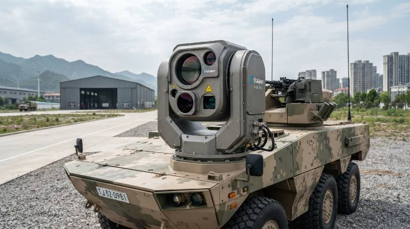
Threat Spectrum & Sensing Physics: The Five-Vector Benchmark for Threat Alerting
Modern combat spaces feature varied optical threats, ranging from legacy 1064nm Q-switched designators to agile 1535nm Erbium-glass rangefinders and modulated beam-rider missile links. Evaluating these threats requires a systematic methodology that balances detection with size, weight, power, and cost constraints.
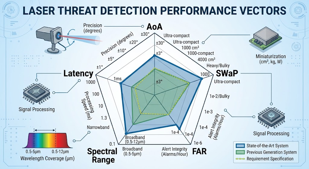
Stalaser assesses survivability payloads using the Five-Vector Optoelectronic Threat Discrimination Architecture:
- Vector 1: Multi-Octave Spectral Selectivity (Resolving Bands I through IV without blind spots).
- Vector 2: Angular Bearing Resolution (AoA) vs. SWaP (Eliminating heavy scanning mechanics).
- Vector 3: High-Clutter Solar Rejection (Preserving SNR ≥ 15 dB under 100,000 Lux ambient daylight).
- Vector 4: Deterministic Kill-Chain Latency (Executing FPGA threat correlation in under 15 ms).
- Vector 5: Thermal Stability Envelope (Retaining calibrated responsivity from -40°C to +70°C).
Multi-Band Spectral Discrimination: 532nm to 1550nm Laser Intercept
Optical threats operate across distinct physical bands, each demanding precise semiconductor and optical substrate selections:
- Band I (532 nm): Frequency-doubled Nd:YAG lasers used in maritime target designating and optical dazzling [Pulse width: 8–15 ns, peak power: 1–10 MW]. Silicon PIN or APD architectures capture this visible regime with high quantum efficiency (> 70%).
- Band II (800 nm – 980 nm): Gallium Arsenide (GaAs) laser diode arrays driving semi-active beam-rider anti-tank guided missiles (ATGMs). These systems utilize spatial-position-encoded pulse-repetition frequencies (PRF) or continuous wave (CW) modulations.
- Band III (1064 nm): Fundamental Nd:YAG military rangefinders and designators [Pulse width: 10–20 ns; Repetition rates: 10–20 Hz for designators, 1–5 Hz for rangefinders]. Standard Silicon drops sharply in responsivity past 1000 nm, necessitating enhanced deep-depletion Silicon or custom InGaAs detector elements.
- Band IV (1535 nm – 1550 nm): Eye-safe emitters matching an erbium glass laser rangefinder and Raman-shifted sources [Pulse width: 5–10 ns; Standoff range: > 5 km]. Indium Gallium Arsenide (InGaAs) photodetectors are mandatory here to ensure high detectivity (D^* ≥ 1012 cmcdotHz1/2/W).
Our manufacturing integrates custom optical bandpass interference coatings directly onto front optical surfaces. These multi-cavity dielectric stacks reject out-of-band background solar clutter while transmitting target threat bands with > 90% transmission efficiency.
Angle of Arrival (AoA) Resolution: Differential Shadow Masking vs. Focal Plane Arrays
Pinpointing laser bearing coordinates enables combat vehicles to cue active protection effectors or train obscuration countermeasure turrets directly at the threat source. In defense optronics, systems engineers face an architectural choice: staring Focal Plane Arrays (FPAs) or multi-element Differential Shadow Masking.
Staring FPAs deliver sub-degree angular accuracy, but they introduce severe penalties: thermal management overhead, excessive weight, slow readout rates (often 30–60 Hz frame limits), and payload costs that limit widespread adoption. For responsive protection systems, waiting a full 33 ms frame integration cycle to register a threat pulse adds unacceptable latency to the kill chain.
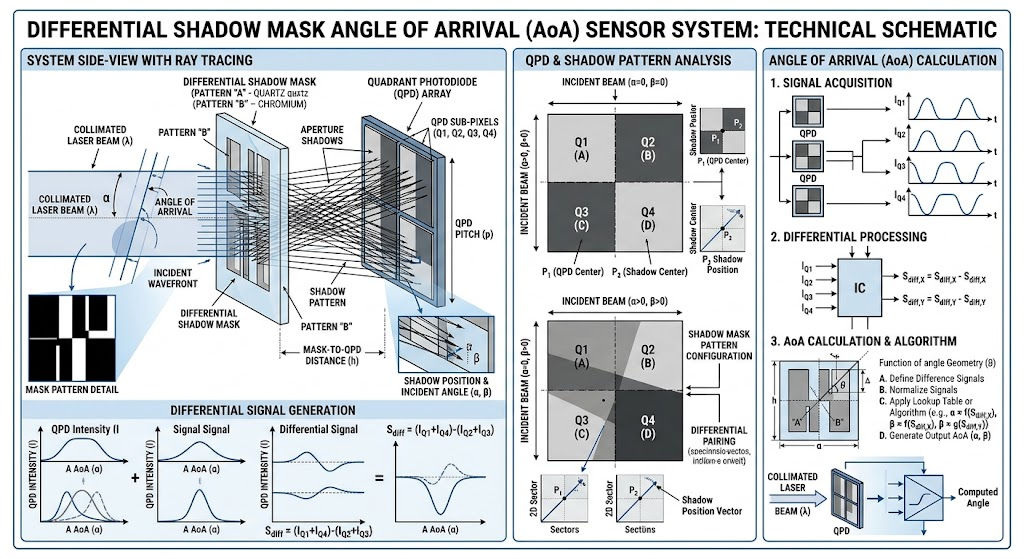
Stalaser utilizes a multi-quadrant Differential Shadow Mask topology. By placing a micro-machined physical shadow mask above precision-tilted photodiode arrays, an incoming wavefront casts an optical shadow across adjacent detector segments:
AoA Calculation Principle: The relative photocurrent ratio between adjacent quadrant photodiodes (IA, IB, IC, ID) establishes incident azimuth (thetax) and elevation (thetay) angles via transfer functions:
thetax = f((IA – IB / IA + IB)), thetay = f((IC – ID / IC + ID))
This approach achieves an Angle-of-Arrival resolution of ±3.5° azimuth and ±5.0° elevation [Collimated 1064nm beam, irradiance ≥ 1 W/m², 25°C] without using heavy optical trains or thermal stabilization. The total optical aperture weighs under 80 grams while delivering an analog response in nanoseconds.
Embedded Low-SWaP Architecture: Designing Sub-300g LWR Modules for Optronic Gimbals
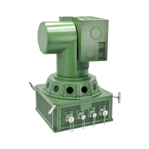
Legacy defense systems split the warning architecture into two separate enclosures: an optical sensor head placed on the exterior superstructure and a bulky, 4–6 kg central Electronic Processing Unit (EPU) mounted deep within the hull. This architecture adds significant cabling, introduces multi-millivolt parasitic RF noise on unamplified analog feeds, and consumes valuable payload volume.
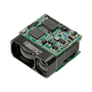
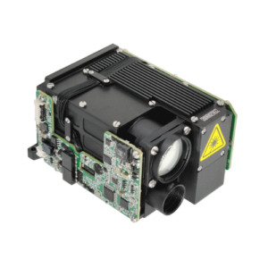
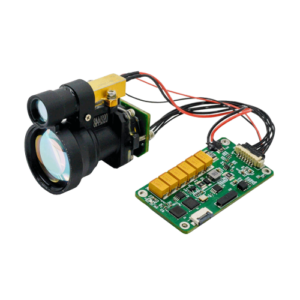
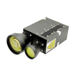
Modern weapon systems require compact designs. Stalaser consolidates the entire signal acquisition, analog front-end (AFE), and digital classification pipeline directly into a unified sensor head weighing under 285 grams [Volume: 74 × 68 × 52 mm, IP67 sealed]. This level of integration enables simple deployment on weight-critical platforms, such as small turrets, remote weapon stations (RWS), and drone UAV payloads.
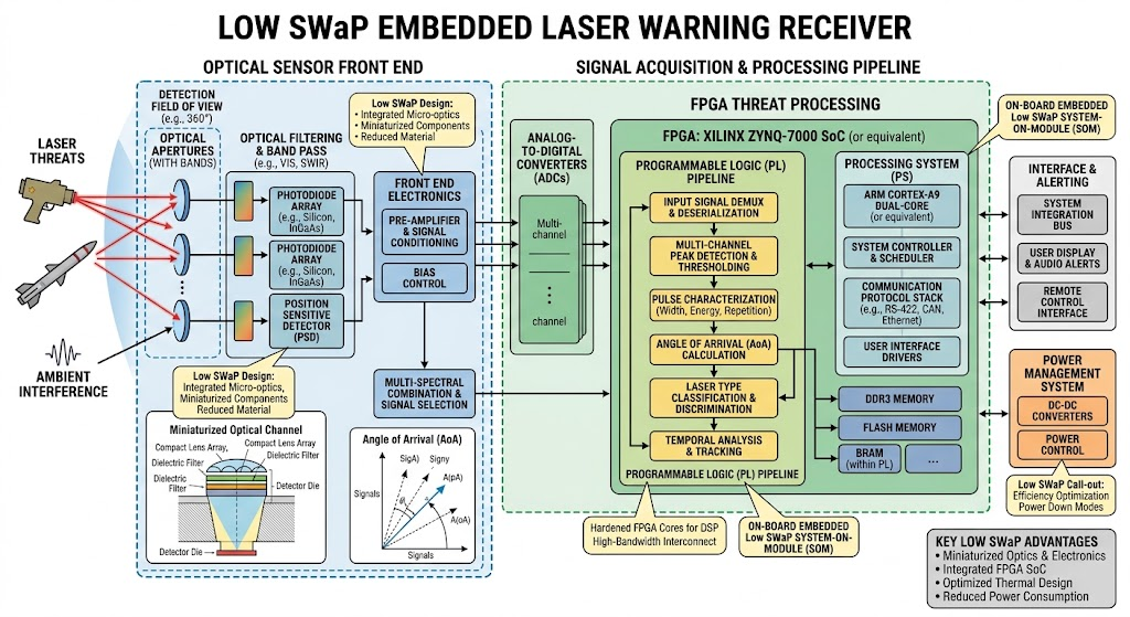
Inside the module, raw high-speed analog current pulses undergo amplification via multi-stage low-noise transimpedance amplifiers (TIAs). Fast differential comparators convert valid fast-rise signals into digital pulse strings, which are fed directly into an onboard field-programmable gate array (FPGA).
The FPGA measures pulse width, extracts pulse repetition interval (PRI), and correlates incoming pulse trains against a stored, field-upgradable threat library [Threat library capacity: > 256 programmable emitter profiles]. All processing runs internally, drawing less than 4.2 W total steady-state power.
Application Sweet Spot vs. When NOT Recommended
Engineering integrity means recognizing the operational boundaries of our optoelectronic systems. Selecting the correct architecture ensures platform survival without over-engineering simple applications.
Cleanroom Manufacturing and Environmental Qualification for Tactical Environments
Semiconductor detectivity degrades rapidly when exposed to micro-particulates, moisture, or flux residues. Stalaser maintains manufacturing and alignment operations within certified Class 10,000 (ISO 7) cleanroom production suites, with critical micro-assembly performed under ISO 5 laminar flow clean benches.
Our microelectronics assembly utilizes wedge wire-bonding to secure silicon and InGaAs dies to custom low-expansion ceramic carriers. This layout suppresses thermal stress mismatches under mechanical shock. Every internal joint is enclosed within dry nitrogen backfilled chambers, producing an environmentally hermetic seal that meets strict ISO 9001:2015 quality standards.
We review every stage of component placement with high-resolution automated optical inspection (AOI) to confirm correct spatial alignment across multi-facet optical windows, ensuring uniform angular response across the entire field of view.

Dynamic Thermal Drift Compensation & Closed-Loop APD Bias Control (-40°C to +70°C)
Avalanche Photodiodes (APDs) and high-sensitivity InGaAs PIN diodes exhibit gain variations over wide temperature swings. If the reverse bias voltage remains fixed while ambient temperatures drop to -40°C, avalanche breakdown can occur prematurely, saturating the channel. Conversely, at +70°C, detector responsivity drops significantly, degrading sensitivity [Threshold sensitivity loss > 12 dB without bias compensation].
Bulky, power-hungry Thermo-Electric Coolers (TECs) add thermal dissipation bottlenecks inside sealed sensor heads. Instead, Stalaser uses dynamic closed-loop bias voltage regulation managed by an integrated DSP:
- Integrated precision thermistors continuously track temperature changes directly on the photodiode ceramic carrier [Tres ≤ ± 0.1°C].
- The onboard DSP cross-references these temperatures against factory-calibrated responsivity curves stored in non-volatile memory.
- A high-voltage, low-ripple buck-boost converter modulates the APD bias voltage in real time [Voltage range: 45V to 220V, drift error ≤ 0.05%].
This active control loop maintains consistent irradiance detection thresholds (≤ 0.1 W/m² [1064nm, 15 ns pulse]) across the entire -40°C to +70°C operational envelope while consuming less than 120 mW of circuit power.
MIL-STD-810H & MIL-STD-461G Qualification Protocols
Tactical deployment demands resilience against rough handling, rough terrain, and electronic warfare environments. Stalaser hardware completes rigorous third-party environmental qualification under standard military test regimes:
- Ballistic & Pyrotechnic Shock: Verified under MIL-STD-810H Method 516.8 [Test severity: 40g, 11 ms half-sine pulse along all 3 orthogonal axes; Pyrotechnic peak: 1,000g at 1,000–5,000 Hz].
- Tactical Vibration Profiles: Tested against MIL-STD-810H Method 514.8, Category 20 (ground tracked combat vehicles) and Category 24 (tactical rotary-wing aircraft) for 8 hours continuous sweep per axis.
- Solar Radiation Exposure: Evaluated to Method 505.7 (1,120 W/m² actinic spectral distribution) to confirm no degradation or fogging of internal optical cements or exterior window coatings.
- EMI/EMC Immunity: Qualified under MIL-STD-461G, including RS103 (radiated field susceptibility tested up to 200 V/m across 2 MHz–18 GHz bands) and CE102 (power lead conducted emissions). Internal nickel-iron Mu-Metal and copper shielding cans isolate low-noise transimpedance inputs from nearby high-frequency vehicle transmitters.
Applying advanced electro-optical technology allows these systems to deliver high optical sensitivity alongside broad electromagnetic survivability.
Sensor-to-Effector Kill Chain: Interfacing Countermeasures and Turret Buses
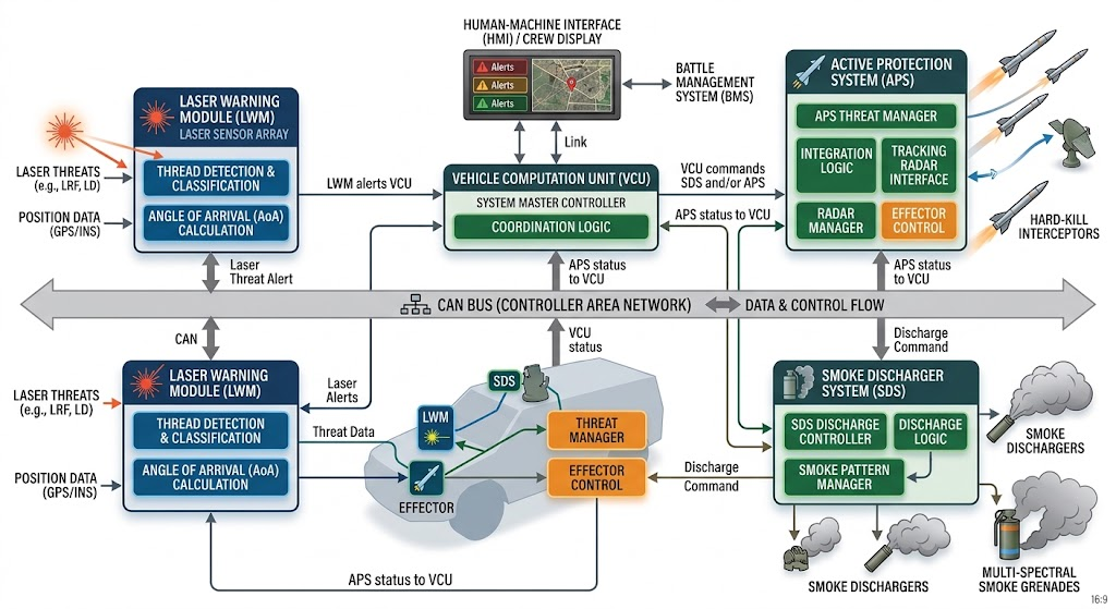
Detecting a laser threat provides limited tactical value if alert data cannot reach vehicle defense systems in time to defeat incoming munitions. In a typical ATGM engagement, a targeting crew may designate a target with a laser rangefinder module, followed by an anti-tank missile reaching impact in roughly 2 to 5 seconds.
Every millisecond saved inside the onboard warning system expands the time window for defensive measures: deploying multispectral aerosol smoke screens, slewing hard-kill interceptors, or initiating directional laser dazzlers.
Deterministic Bus Latency & Real-Time Protocol Implementation (≤ 15 ms)
To eliminate latency bottlenecks, Stalaser designs use deterministic, bare-metal FPGA timing sequences that avoid the variable scheduling delays of standard operating systems. From the instant a threat laser wavefront strikes the optical aperture to the transmission of a verified threat alert, the signal follows an unyielding execution pipeline:
- Photon Conversion & Analog Differentiation (0.00 to 0.05 µs): Photodiode outputs generate a voltage spike; analog high-pass filters strip out low-frequency solar ambient light.
- Pulse Capture & PRI Timestamping (0.05 to 5.0 ms): The FPGA internal timing engine records arriving pulses with sub-nanosecond accuracy (tres ≤ 1 ns), accumulating the consecutive pulses needed to confirm a steady repetition interval.
- Library Threat Correlation (5.0 to 10.0 ms): Extracted PRF sequences are checked against onboard threat tables to confirm whether the emitter is a rangefinder, tracking illuminator, or beam-rider platform.
- Bus Message Serialization (≤ 15.0 ms): The system generates a structured CAN 2.0B / CAN-FD frame or RS-422 packet and transmits it across the primary vehicle interface [CAN baud rate: 1 Mbps; RS-422: up to 921.6 kbps].
By enforcing a maximum latency of 15 milliseconds [Tested: 100-event batch, logic analyzer measurement, direct trigger to line driver out], the host Combat Management System (CMS) receives clean, prioritized threat alerts in time to coordinate active platform defense.
Hardcore Engineering Defense FAQ: Obscurants, False Alarm Rates, and Threat Decoding
Q: How does Stalaser prevent false alarms caused by solar reflections, lightning, and muzzle flashes?
We apply a three-stage discrimination architecture:
- Optical Stage: Dielectric interference coatings reject out-of-band sunlight and pass only critical threat wavelengths (532, 800–980, 1064, and 1535/1550 nm).
- Analog Stage: High-pass differential transimpedance stages isolate optical pulses with fast rise times (< 25 ns), discarding slower transitions from muzzle flashes, lightning events, and solar glare.
- Digital Stage: The onboard FPGA validates pulse continuity and PRF signatures against active threat profiles, discarding non-coherent, uncorrelated optical spikes.
Spec Metric: False Alarm Rate (FAR) < 1 per 24 hours under continuous 100,000 Lux unattenuated solar radiation [Tested with continuous solar simulator exposure, MIL-STD-810H Method 505.7].
Q: How does the system resolve Angle-of-Arrival (AoA) without adding heavy optical lenses?
The system uses an array-based differential shadow mask placed above matched, precision-angled photodiode segments within an integrated compact head. By measuring the fractional differences in illumination and signal phase between adjacent quadrant elements, the onboard processor calculates incident elevation and azimuth angles without needing compound lens groups, mechanical derotators, or heavy staring arrays.
Spec Metric: AoA Accuracy: ±3.5° horizontal azimuth, ±5.0° vertical elevation across a 90° quadrant per sensor head [Tested using collimated 1064nm reference source at 10 W/m² irradiance]. Four distributed heads deliver seamless 360° hemispherical coverage.
Q: How is thermal sensitivity drift compensated across the -40°C to +70°C envelope?
Rather than using high-power Thermo-Electric Coolers (TECs), we integrate embedded on-substrate thermistors paired with dynamic closed-loop bias voltage regulation managed by the onboard DSP. The controller continuously recalculates and adjusts APD bias voltages against stored factory calibration look-up tables.
Spec Metric: Maintains sub-microvolt pulse detection sensitivity and an irradiance threshold ≤ 0.1 W/m² [1064nm, 15 ns pulse width] throughout the complete -40°C to +70°C operating range.
Defense Procurement, Quality Assurance, and Dual-Sourcing Framework
Defense supply chains require predictable production schedules, export flexibility, and long-term part availability. Stalaser maintains rigorous manufacturing standards to simplify procurement and support long-lifecycle vehicle upgrade programs.
| Pillar | Operational Protocol | Delivery Benchmark |
|---|---|---|
| Evaluation Lead Time | Standard benchtop evaluation units with functional GUI and serial breakout boards | 2 to 3 weeks (AOG / Express shipping) |
| Series Production | Volume production runs (100–1,000+ units per delivery schedule) | 8 to 12 weeks to first lot dispatch |
| Supply Chain Continuity | Dual-sourced semiconductor wafers, optical coatings, and processing chipsets to mitigate single-supplier dependencies | Guaranteed 10-year production & maintenance support |
| Compliance & Standards | Manufactured under ISO 9001:2015, MIL-STD-810H, MIL-STD-461G, IEC 60825-1, RoHS, and REACH guidelines | 100% Certificate of Conformance (CoC) & full factory acceptance reports |
Accelerating Platform Deployment: 3-Step Action Funnel for Systems Integrators
Integrating mission-critical optoelectronics into turret configurations, RWS pods, or unmanned aerial gimbals demands straightforward technical evaluation. Integrators can evaluate Stalaser systems using our streamlined 3-step qualification path:
Step 1: Download Interface & Mechanical ICD
Review our comprehensive Interface Control Document (ICD). Examine optomechanical envelopes, mounting bolt patterns, connector pin assignments (Amphenol / Glenair mil-spec series), and CAN/RS-422 communications protocols.
Step 2: Request an Application-Specific Evaluation Unit
Specify platform integration requirements: select operational wavelength profiles (e.g., dedicated 1064nm & 1535nm vs. full Bands I–IV multi-spectral coverage) and the field-of-view configuration (single-head 90° quadrant vs. four-head 360° arrays). Evaluation units arrive ready for bench testing, complete with reference test software, SDK libraries, and 3D STEP models.
Step 3: Direct Engineering Consultation & RFQ
Collaborate directly with our optronic manufacturing team to finalize your target bill of materials, define custom enclosure requirements, and plan pilot integration schedules.
Upgrade Your Vehicle Defense Architecture
Evaluate low-SWaP laser threat detection systems engineered for tactical vehicles, gimbals, and remote weapon stations. Contact our technical team for ICD packages, evaluation hardware, and firm quotations.