

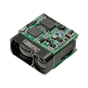
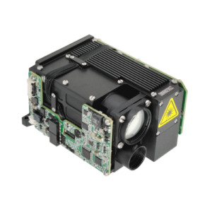
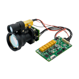
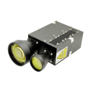
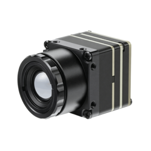
Parametric Quick-Spec & Engineering Decision Matrix
Modern defense fire-control systems demand strictSize, Weight, Power, and Cost (SWaP-C) optimization alongside survivability under continuous mechanical shock. When selecting a laser rangefinder module for tactical payloads, optoelectronic parameters must be evaluated directly against standard target cross-sections and atmospheric extinction profiles.
| Parameter / Feature | Benchmark Value | Strict Test Condition | Sweet Spot Application | When NOT Recommended |
|---|---|---|---|---|
| Laser Wavelength | 1535 nm ±10 nm | Erbium-doped phosphate glass, passive Q-switched | Covert targeting immune to Gen II/III NVGs | Active laser illumination / SWIR imaging |
| Measurement Range (Vehicle) | 3,000 m to 8,000 m | 2.3m x 2.3m target, 10% diffuse albedo, V ≥ 15 km, SNR ≥ 15 dB | Armored vehicle FCS, tactical UAV gimbals | Ultra-short proximity detection (< 15 m) |
| Range Accuracy | ±1.0 m | Standard deviation of 100-shot average, -40°C to +65°C | Sniper computer integration, artillery spotting | Sub-millimeter industrial metrology |
| Beam Divergence | ≤ 0.5 mrad (1/e²) | Collimated doublet, athermal housing mount | Narrow cross-section targeting at stand-off ranges | Wide-angle proximity obstacle avoidance |
| Optical Boresight Stability | ≤ 0.15 mrad drift | Continuous thermal soak across -40°C to +65°C | Weapon-mounted high-recoil optics, multi-sensor gimbals | Non-critical consumer optical devices |
| Repetition Rate | 1 Hz continuous, 5 Hz burst | Burst duty cycle ≤ 10 s, thermal passive equilibrium | Loitering munition terminal phase ranging | High-density 3D LiDAR point cloud scanning (> 100 kHz) |
| Mechanical Shock Survival | 1,200 g to 1,500 g, 0.5 ms | MIL-STD-810H Method 516.8, half-sine, 3 axes | Direct barrel-mounted small arms, autocannon mounts | Stationary benchtop setups |
| Module Mass & Power | 38 g to 45 g; ≤ 2.5 W active | 3.3V / 5V DC input, standby consumption < 0.1 W | Handheld thermal binoculars, micro-UAV payloads | High-power shipboard tracking installations |
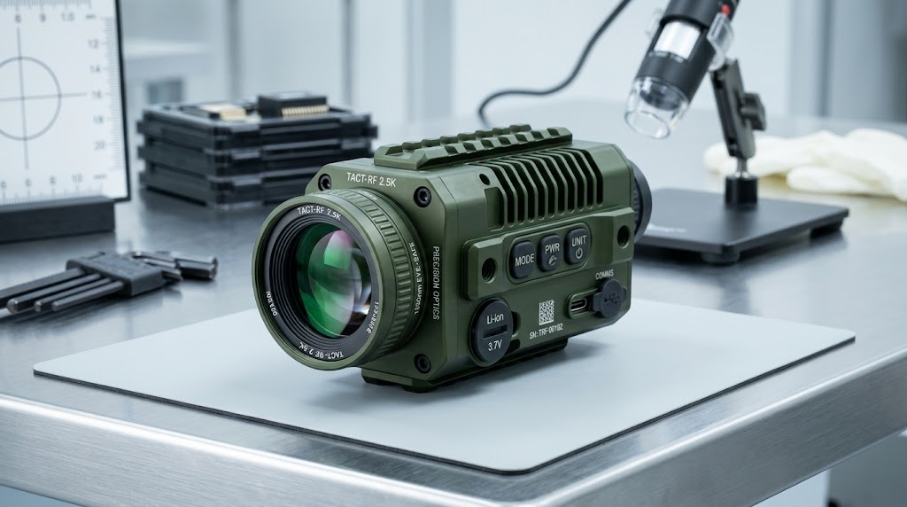
The 5-Pillar Military LRF Module Evaluation Metric
To avoid integration roadblocks during payload qualification, optical engineering teams use a deterministic qualification framework. The 5-Pillar Military LRF Module Evaluation Metric provides a quantitative standard to ensure payloads survive operational stresses while meeting detection criteria.
The 5-Pillar Metric Defined: An empirical evaluation framework designed to benchmark tactical rangefinders across spectral stealth, energy concentration, optomechanical shock retention, probabilistic atmospheric penetration, and deterministic latency.
In our manufacturing experience across multiple defense programs, evaluating modules through this framework isolates systemic integration errors early in the qualification cycle.
- 1. Wavelength & Detection Survivability: Operating strictly in the Short-Wave Infrared (SWIR) 1535 nm window ensures full compliance with IEC 60825-1:2014 Class 1 eye safety. This wavelength remains completely invisible to enemy combatants using legacy Silicon Gen II/III Image Intensifier (I2) night-vision goggles.
- 2. Energy Concentration (Aperture-to-Divergence Ratio): Modules must maintain a beam divergence ≤ 0.5 mrad [Full Width at Half Maximum (FWHM), 25°C]. At 3,000 meters, this limits the spot footprint to 1.5 meters, concentrating optical energy within the NATO standard vehicle target profile (2.3m x 2.3m).
- 3. Dynamic Shock & Boresight Retention: Optical boresight must maintain pointing accuracy within < 0.15 mrad [Residual drift after 1,200 g half-sine shock pulses per MIL-STD-810H Method 516.8]. Any broader shift degrades co-alignment with primary thermal sights and narrow-field-of-view day cameras.
- 4. Real-World Optical Atmospheric Benchmark: Ranging range must achieve a Probability of Detection (PoD) ≥ 90% [Target: 10% diffuse albedo, standard rural visibility V = 15 km, calculated via Kruse model, SNR ≥ 15 dB]. Laboratory vacuum performance metrics provide no guarantee of real-world functionality in turbulent battlefield air.
- 5. Deterministic Real-Time Polling Latency: Execution command-to-data-output latency must remain ≤ 12 ms [Asynchronous UART / RS-422 serial polling, 115,200 bps baud rate, jitter < 1 ms]. Predictable response timing is mandatory for lead-angle ballistic computing loops in weapon fire-control systems.
Tactical Core Technologies: 1535nm Er:Glass Transceivers vs. Legacy Architectures
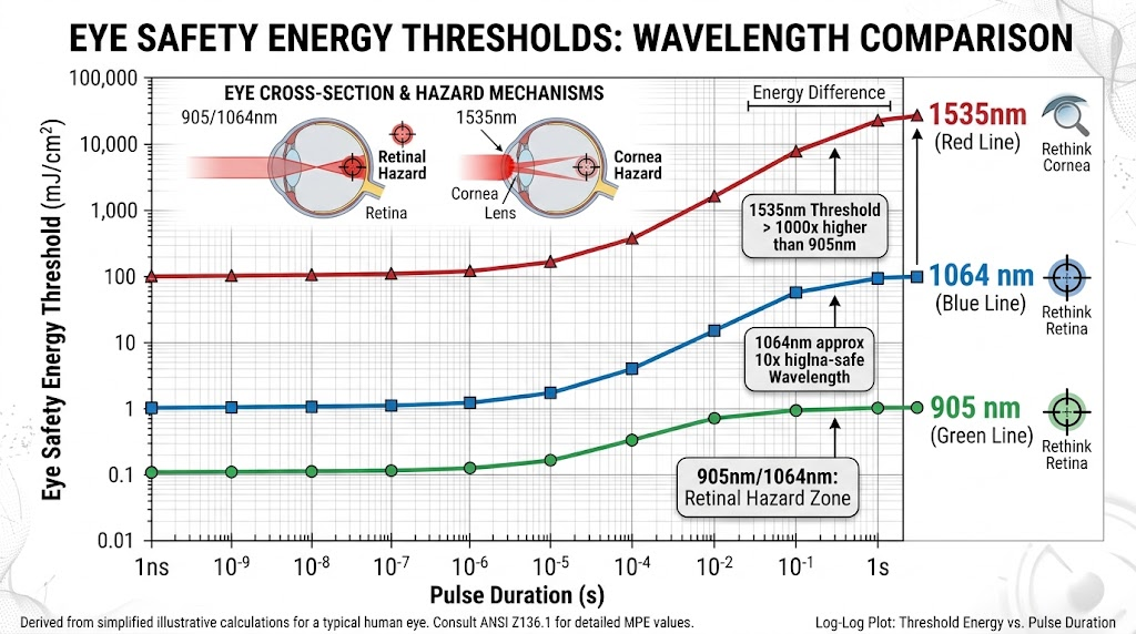
Selecting an operational wavelength dictates both the survivability of the operating warfighter and the payload’s physical mass. Defense optronics have shifted systematically away from 905 nm semiconductor diodes and 1064 nm solid-state crystal lasers in favor of 1535 nm erbium glass laser rangefinder architectures.
Near-infrared (NIR) 905 nm semiconductor diodes suffer from poor atmospheric penetration and wide divergence profiles. Furthermore, 905 nm photons exhibit intense blooming on enemy Gen II/III image intensifiers, immediately compromising operator positions. While high-energy 1064 nm Nd:YAG lasers deliver extended range, their transmission through the ocular cornea directly into the retina poses a severe blinding hazard. As a result, 1064 nm systems require safety locks during troop training, along with heavier optical assemblies.
Conversely, 1535 nm photons are absorbed primarily within the cornea and lens, preventing energy concentration onto the sensitive retina. This allows for nearly 4 orders of magnitude higher optical emission limits under IEC 60825-1:2014 standards while remaining fully Class 1 eye-safe. Combined with sensitive Indium Gallium Arsenide (InGaAs) Avalanche Photodiode (APD) receivers, Stalaser modules deliver sustained multi-kilometer target acquisition in an ultra-compact footprint. In complex defense systems, these ranging modules are frequently cross-slaved to an external military laser target designator to pass target coordinates directly into terminal precision-guided munitions.
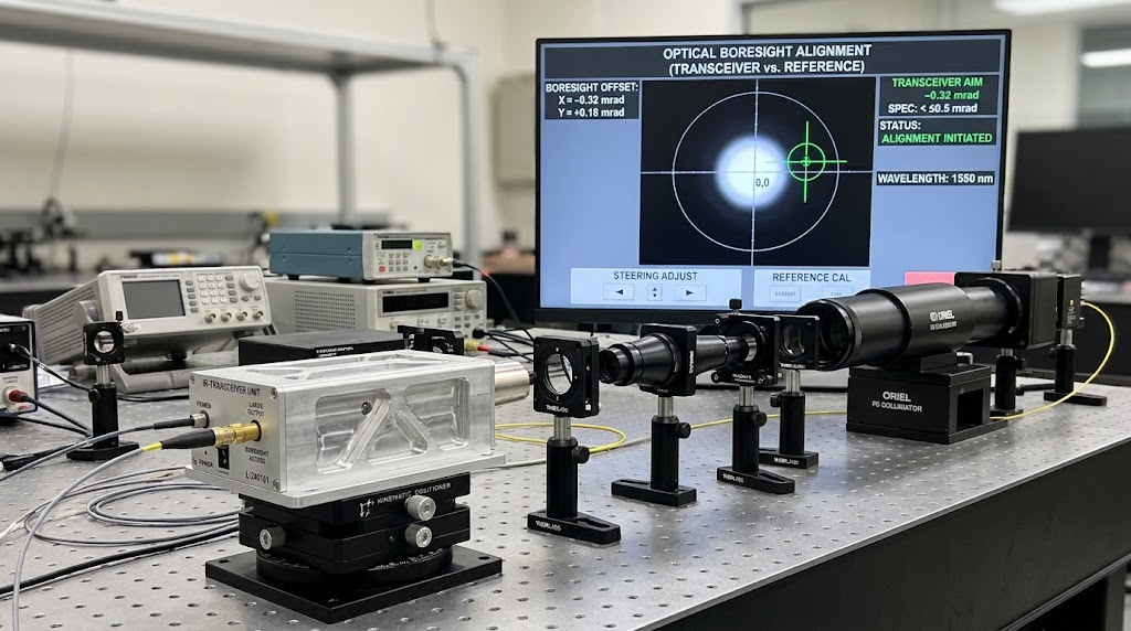
Optomechanical Defense: Zero Recoil Shift & Thermal Drift Athermalization
Stalaser solves these optomechanical challenges by incorporating an athermalized structural sleeve machined from low-expansion Invar alloys paired with high-grade optical cemented doublets. This configuration counteracts differential thermal expansion, keeping focal plane displacement well within the Rayleigh range of the collimator. The Erbium-glass emitter’s thermal wavelength drift is controlled to < 0.05 nm/°C, preventing the signal from wandering outside the narrow spectral passband of the receiver’s optical filter.
Empirical Test Bench Data: During dynamic environmental qualification tests under MIL-STD-810H Method 501.7/502.7 (Thermal Soak from -40°C to +65°C at 1°C/min rate of change), Stalaser tactical modules recorded a maximum boresight deviation of 0.12 mrad. Following 1,500 g half-sine mechanical shock firing cycles (MIL-STD-810H Method 516.8), boresight retention was preserved within < 0.15 mrad across all coordinate axes.
Collimation optics are secured using spatial flexure mountings and military-grade structural adhesives (compliant with NASA low-outgassing standards). This eliminates mechanical backlash and prevents unrecoverable boresight deviation during rapid-fire small-arms operation or autocannon vibration profiles.
Electro-Optical Defense Integration: Gimbals, Soldier Sights, and Unmanned Systems
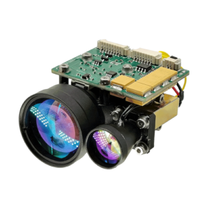
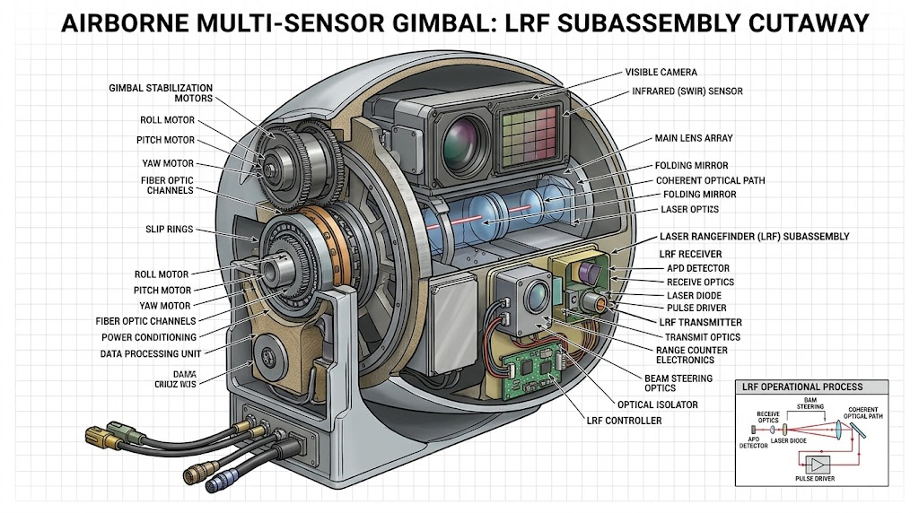
Sub-system packaging requires careful attention to size, weight, and electrical isolation. Stalaser modules, weighing between 38 g and 45 g, are purpose-built for seamless integration into multi-sensor gyro-stabilized gimbals, uncrewed platforms, and crew-served weapon sights.
When engineering drone UAV payloads, electrical cross-talk from brushless gimbal motors and onboard digital video links can compromise sensitive APD signal paths. Our modules feature internal electromagnetic interference (EMI) shielding compliant with MIL-STD-461G (RE102, RS103). High-density low-profile mezzanine connectors or flexible ribbon cables route through the tight mechanical limits of multi-axis gimbal yokes without adding mechanical torque.
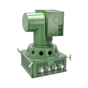
In modern armored vehicle integration, ranging sensors operate within comprehensive survivability networks. Armored vehicle platforms frequently link these precise ranging modules directly with an onboard laser warning system. This configuration automatically slews the sensor turret toward hostile laser designators, rapidly calculating counter-fire ballistic solutions with microsecond precision.
Application Sweet Spot vs. When NOT Recommended
Selecting laser rangefinder components requires balancing physical and electronic constraints. Clear operating boundaries ensure modules perform reliably in their intended environments.
OEM Manufacturing Standards: Automated Cleanrooms, MIL-STD Testing, & Supply Chain Stability
Precision electro-optics cannot be reliably assembled in standard electronic factory environments. Stalaser produces all tactical rangefinder modules inside certified ISO Class 7 (Class 10,000) cleanroom environments with dedicated laminar flow benches rated to ISO Class 5.
Automated optical benches utilize collimated laser interferometers to align the receiver lens group to the active detector surface. Robotic five-axis dispensers apply optical epoxy with micron-level precision, followed by automated UV cure schedules to eliminate structural shrinkage. Surface-mount electronic boards comply with IPC-A-610 Class 3 standards to ensure high solder joint integrity under sustained ballistic vibration.
To insulate prime defense contractors from volatile global supply disruptions, Stalaser maintains dual-source qualification for critical components, including raw Erbium-doped phosphate glass, custom InGaAs avalanche photodiodes, and specialized optical thin-film anti-reflective coatings. Our production workflows strictly avoid ITAR restrictions, ensuring smooth international export through certified dual-use commercial defense trade channels.
Hardcore Engineering Defense FAQ
Below are technical responses to common integration questions raised by system architects and electro-optical payload engineers during design reviews.
Q: How does Stalaser control boresight shift under extreme thermal swings (-40°C to +65°C)?
Thermal drift is governed by differential thermal expansion across the optical barrel and sensor mount. Stalaser utilizes an athermalized optical architecture combining low-expansion Invar structural sleeves with balanced dual-lens collimation. Laser diode thermal wavelength shift (< 0.05 nm/°C) is pre-compensated across the bandpass filter window, maintaining boresight stability to within < 0.15 mrad and avoiding signal extinction at operating temperature limits. [Spec Metric: Boresight drift < 0.15 mrad across -40°C to +65°C; diode shift < 0.05 nm/°C]
Q: How does the module handle backscatter from fog, rain, or battlefield dust?
Our signal processing pipeline incorporates hardware-level Time-Programmed Gain (TPG) alongside digital multi-echo discrimination algorithms. Near-field backscatter (dust, rotor-blade vortex spray, smoke) is gated out via user-configurable minimum ranging thresholds (Rmin blanking) combined with target return peak extraction, ensuring the receiver captures target signatures even under conditions with low signal-to-noise ratios (< 10 dB). [Spec Metric: Multi-echo discrimination with operational SNR threshold < 10 dB and configurable Rmin blanking]
Q: What is the communication latency and timing jitter over serial links?
Stalaser LRF modules feature dedicated 3.3V TTL / RS-422 serial interfaces running up to 115,200 bps. Ranging command execution to data output latency is deterministic: ≤ 12 ms in single-pulse mode with < 1 ms protocol jitter, allowing direct synchronization with real-time gimbal inertial navigation systems (INS) and weapon fire-control computers. [Spec Metric: Execution latency ≤ 12 ms, timing jitter < 1 ms at up to 115,200 bps baud rate]
Defense Procurement & OEM Supply Chain Assurance
Deploying defense systems requires predictable delivery schedules and complete traceability. Stalaser provides commercial clarity to help procurement officers and programs stay on schedule.
- Evaluation Sample Lead Times: Pre-configured engineering qualification kits ship in 7 to 14 business days. Standard production batch shipments of up to 1,000 units are fulfilled within 4 to 6 weeks.
- Evaluation Support: Every sample kit includes an RS-422/USB interface test jig, real-time diagnostic software, pinout evaluation boards, and complete 3D CAD STEP mechanical models.
- Supply Chain Redundancy: Critical supply chains feature secondary qualification for active optical elements, raw laser glass materials, and optoelectronic transceivers.
- Industry Standards Compliance: Manufactured under ISO 9001:2015 certified quality systems. Certified to meet MIL-STD-810H (Shock, Vibration, Temp Soak), IPC-A-610 Class 3, IEC 60825-1:2014, and current RoHS/REACH environmental mandates.
3-Step Frictionless Evaluation & Integration Action Funnel
Simplify your payload development with Stalaser’s streamlined, three-step integration pipeline:
- Step 1: Download Interface Control Document (ICD) & Pinout Geometry
Review mechanical mounting models, optical clear aperture footprints, electrical pinouts, and UART communication protocols directly against your payload envelope. - Step 2: Request an In-Stock Field Evaluation Kit
Integrate an engineering sample with your sensor payload using our dedicated test jig to run live baseline verification on dynamic target ranges and environmental test chambers. - Step 3: Direct Integration Consultation with Stalaser Optics FAE Team
Collaborate directly with our senior electro-optical system engineers to customize athermal mounting flexures, reticle offsets, or firmware-level multi-echo gating algorithms for your specific mission profile.
Ready to Accelerate Your Electro-Optical Payload Integration?
Engage our Field Application Engineering team to request Interface Control Documents (ICD), CAD files, or field evaluation hardware.