

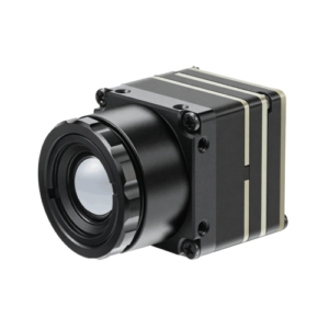


Engineering Overview: Calibrating High-Precision Laser Ranging Modules
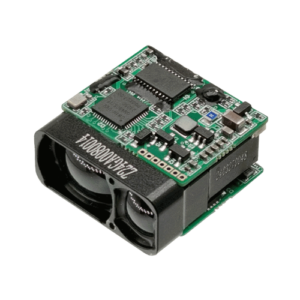
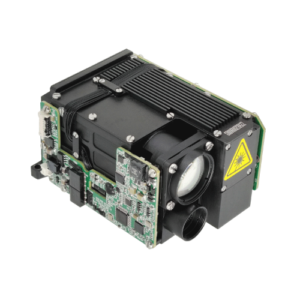
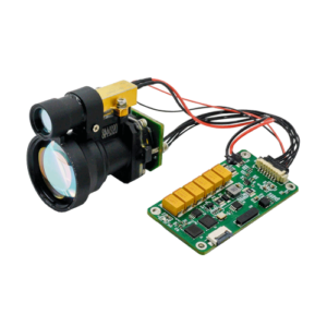
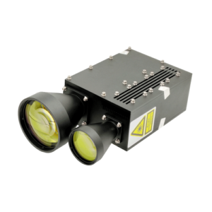
Calibrating an OEM pulsed laser ranging module requires synchronizing optomechanical alignment, internal propagation delays, detector bias voltages, and atmospheric compensation into an integrated hardware routine. Achieving sub-decimeter accuracy across multi-kilometer baselines demands correcting for hardware Time-of-Flight (ToF) zero-point shifts, thermal drift in the Avalanche Photodiode (APD) receiver, and beam divergence deviations.
In high-performance optoelectronic systems, ranging errors do not originate from a single source. They stem from a complex interaction of optical transceiver parallax, internal Time-to-Digital Converter (TDC) clock jitter, and non-linear target albedo reflectivity.
Integrators working with advanced electro-optical laser measurement technology must move beyond basic single-point offset trimming. Accurate field operations require an end-to-end, multi-parameter calibration architecture executed at the hardware register level.
The 4-Vector OEM Laser Rangefinder Calibration Framework
Standard industrial testing often treats laser ranging calibration as a simple linear offset subtraction. However, defense fire-control systems, long-range targeting pods, and aerospace payloads experience multi-axis physical variables that quickly invalidate static offsets.
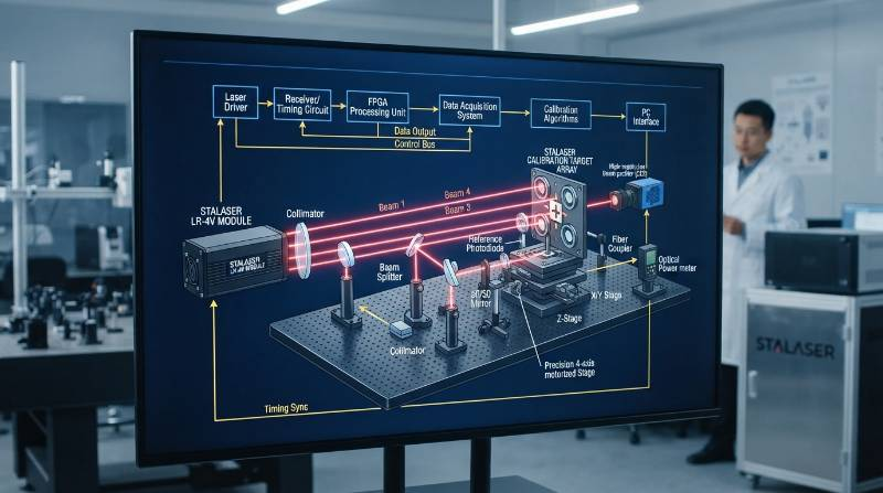
Stalaser establishes the 4-Vector OEM Laser Rangefinder Calibration Framework to isolate and rectify every physical and electro-optical error source systematically.
4-Vector OEM Calibration Framework: A deterministic metrology model that addresses: (1) Optical Boresight & Parallax Collimation, (2) Internal TDC Hardware Delay Zero-Point (T0), (3) Thermal Look-Up Table (LUT) Voltage Compensation (-40°C to +65°C), and (4) Dynamic Target Albedo Walk-Error Correction.
| Calibration Dimension | Conventional 1-Point Baseline Trim | 4-Vector OEM Calibration Framework |
|---|---|---|
| Optical Alignment | Visual coarse reticle centering (~1.0 mrad) | Off-axis parabolic collimation (≤ 0.2 mrad Tx/Rx to EO/IR) |
| Zero-Point Delay (T0) | Software wrapper offset (host-side subtraction) | Hardware register write to non-volatile EEPROM via UART/RS-422 |
| Thermal Stability | Room temperature baseline only (20°C) | Dynamic multi-point LUT interpolation (-40°C to +65°C) |
| Albedo & Saturation | Fixed single-threshold discriminator | Constant Fraction Discriminator (CFD) / Dynamic Walk Matrix (5%-90%) |
Laboratory Environmental Controls & Metrology Bench Setup
Precision calibration requires strict optical laboratory protocols. Testing must be conducted inside an ISO Class 7 (Class 10,000) cleanroom environment to prevent particulate contamination on sensitive optical window coatings.
The primary metrology bench consists of a pneumatically isolated, honeycomb-core vibration isolation optical table. Ambient environmental conditions must remain stabilized at 20°C ± 1.0°C with relative humidity controlled between 40% and 50% according to NIST metrology guidelines.
Ensure strict adherence to optical safety parameters. While 905nm semiconductor laser diodes operate in the Class 3R/3B category requiring certified safety goggles, a 1535nm erbium-glass laser rangefinder operates in the eye-safe Class 1 spectrum according to IEC 60825-1:2014 standards.
Vector 1: Optical Axis Parallax & Boresight Alignment Protocol
Optical boresight misalignment is the primary cause of target dropout at extended operational ranges. When the transmitter (Tx) beam axis and receiver (Rx) optical axis diverge from each other or from the host EO/IR camera reticle, photon return density drops below the APD detector sensitivity threshold.
Alignment Step-by-Step Execution
- Mount the Module: Secure the rangefinder chassis to a 3-axis micro-positioning kinematic optical mount.
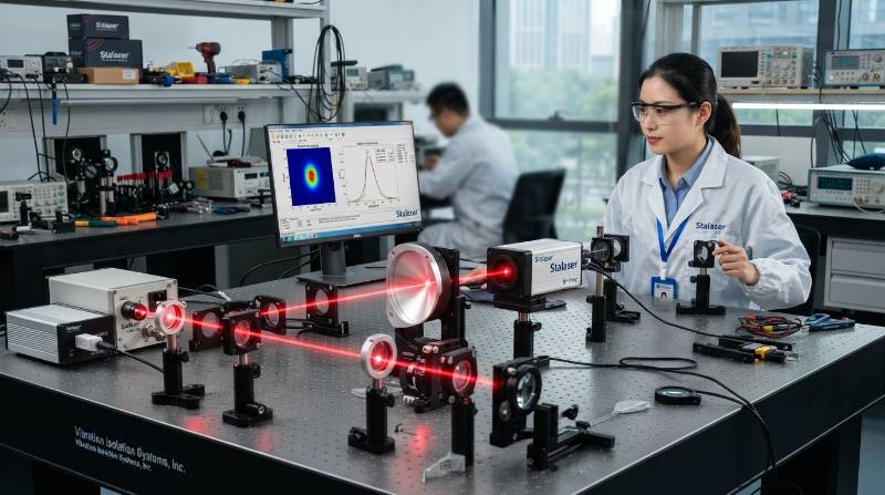
- Collimator Positioning: Align the module to an Off-Axis Parabolic (OAP) reflective collimator equipped with an integrated focal plane reticle.
- Beam Profile Acquisition: Direct the 1535nm or 905nm laser pulses onto an infrared sensor card or a SWIR/CMOS beam profiling camera placed at the focal point.
- Angular Parallax Adjustment: Adjust the module’s fine-pitch mechanical set screws until the optical center of the emitted beam spot converges with the receiver reticle axis to within ≤ 0.2 mrad.
Maintaining divergence under 0.2 mrad ensures that at a 5,000-meter baseline, the laser footprint centroid deviates by less than 1.0 meter from the target crosshair, ensuring maximum echo return to the APD active area.
Vector 2: Internal Time-of-Flight (T0) Delay & Zero-Offset Calibration
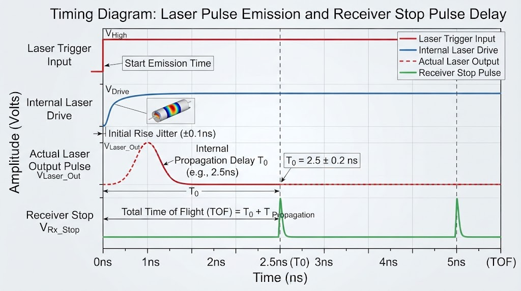
Pulsed Time-of-Flight ranging relies on picosecond-scale optical timing. However, the raw interval measured by the Time-to-Digital Converter (TDC) includes fixed internal hardware propagation delays.
These delays stem from driver switching transit times, avalanche buildup time in the APD, PCB trace transit times, and optical window transmission delays. Without calibration, this fixed propagation delay produces a constant physical distance offset (T0).
The Hardware Delay Equation
The true physical range ($R$) is calculated by removing the internal hardware delay (tdelay) from the measured total elapsed time (traw):
R = (c / 2n) × (traw – tdelay)
Where c is the speed of light in vacuum, and n is the atmospheric group refractive index.
Calibrating the Zero-Point (T0) via Hex Serial Commands
- Position a calibrated Spectralon 80% diffuse reflectance standard at a certified reference distance (Rref = 10.000 m ± 0.002 m).
- Trigger the module via UART / RS-422 at 115200 baud to fire 100 consecutive pulses.
- Read the uncompensated raw range reports returned in the serial hex packet.
- Calculate the constant offset value: Δ R = Rmeasuredavg – Rref.
- Convert Δ R to the corresponding time delay offset value in picoseconds.
- Write the zero-offset value directly into the module’s non-volatile EEPROM register using the calibration command protocol (e.g.,
0xAA 0x55 0x07 0x02 [Data Hex] 0xCS). - Power cycle the unit and query the baseline distance again to verify that Rmeasured = 10.00 m ± 0.05 m.
Vector 3: Thermal Drift Matrix & APD Voltage Gain Tuning (-40°C to +65°C)
Temperature fluctuations introduce non-linear ranging errors and severe sensitivity loss. Two internal subsystems are particularly vulnerable to thermal shifts: the receiver APD detector and the TDC reference clock oscillator.
As ambient temperatures drop to -40°C, the APD breakdown voltage decreases. If the high-voltage bias remains static, the receiver suffers excessive dark noise or enters uncontrolled breakdown. Conversely, at +65°C, higher breakdown voltage lowers receiver gain, degrading the signal-to-noise ratio (SNR) on weak returns.
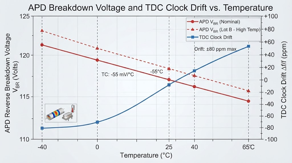
To deliver consistent ranging accuracy across the full laser rangefinder module product line, modules undergo dynamic climatic chamber calibration.
Climatic Chamber Matrix Generation
- The ranging module is mounted inside an automated thermal chamber coupled through an optical flat quartz window to a collimated test bench.
- The chamber cycles through thermal stabilization plateau steps: -40°C, -20°C, 0°C, +25°C, +45°C, and +65°C.
- At each temperature step, an onboard thermistor reads the optomechanical engine temperature.
- The automated calibration suite optimizes the APD bias voltage DAC registers to maintain an optimal signal-to-noise ratio without triggering false alarms.
- Simultaneously, the TDC reference clock frequency drift is measured against a rubidium frequency standard.
- The resulting coefficients populate an internal Look-Up Table (LUT) stored in module flash memory, enabling automatic real-time drift compensation during operation.
Vector 4: Atmospheric Refractive Index & Target Albedo Walk Error Calibration
Target reflectivity variations and atmospheric dynamics introduce errors in long-range metrology systems that hardware zeroing alone cannot fix.
Target Albedo “Walk Error” Correction
Walk error occurs when return signals of varying amplitudes cross a fixed-threshold voltage discriminator at different times. A high-reflectivity target (90% diffuse white) produces a rapid rise time that triggers the comparator earlier than a weak return from a low-reflectivity target (5% dark matte), causing range discrepancies up to ±0.3 meters.
Stalaser resolves this by utilizing Constant Fraction Discriminator (CFD) circuitry combined with digital pulse energy monitoring. During calibration, returns across 5% to 90% target albedos are evaluated to build an internal amplitude-to-range compensation matrix.
Atmospheric Group Refractive Index (ng)
The speed of light through the atmosphere varies with air density. Integrators must apply real-time scale-factor compensation based on barometric pressure ($P$ in hPa) and dry-bulb temperature ($T$ in Kelvin):
(ng – 1) × 106 = (77.6 / T) × (P + 4810 × e / T)
For high-altitude UAV operations, sending updated atmospheric correction factors over the host interface prevents multi-meter scaling errors across extended ranges.
Field Calibration in Sealed Payloads: The Stalaser Digital Closed-Loop Advantage
A persistent challenge for electro-optical payload integrators is maintaining calibration inside hermetically sealed IP67 / MIL-STD pods. Disassembling sealed gimbal enclosures to adjust mechanical set-screws or attach test headers increases integration labor and risks seal degradation.
When deploying modules in demanding UAV gimbal and defense payloads, Stalaser’s Digital Closed-Loop Software Calibration Protocol enables field adjustment through simple serial commands.
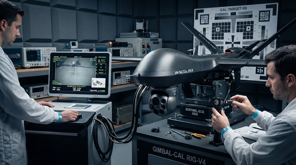
Integrators can recalibrate zero-point offsets, adjust internal range gates, and fine-tune APD sensitivity via TTL/RS-422/RS-232 serial buses while the module remains sealed inside the payload housing. This digital architecture cuts factory integration cycles and makes routine maintenance straightforward.
Frequently Asked Questions (FAQ)
How often should an OEM laser ranging module be recalibrated?
For systems operating under MIL-STD-810H environmental conditions, complete 4-vector verification is recommended every 12 to 24 months. However, if the module experiences mechanical shock exceeding 500g or rapid thermal cycling beyond design envelopes, boresight alignment and zero-offset baseline checks should be performed immediately.
What is the acceptable boresight alignment tolerance for defense-grade payloads?
Standard defense and tactical payloads require a boresight divergence tolerance of ≤ 0.2 mrad between the laser transmitter, the receiver optical axis, and the primary thermal/daylight camera channels. High-precision airborne targeting systems often target ≤ 0.1 mrad to maximize pulse energy concentration on distant targets.
What physical mechanism causes Time-of-Flight ranging drift over temperature?
Thermal drift is primarily driven by temperature coefficients in the APD detector (which alters reverse breakdown voltage and signal rise-times) and frequency drift in the crystal oscillators clocking the TDC. Stalaser mitigates this by integrating internal thermistor sensors that dynamically interpolate factory-calibrated Look-Up Tables (LUTs).
Why is writing zero-offsets to hardware registers better than software subtraction?
Writing offsets directly to non-volatile EEPROM registers ensures that hardware range gating, noise-rejection logic, and Constant Fraction Discriminators operate on true physical pulse timings. Host-side software subtraction leaves low-level signal processing vulnerable to range-gate clipping errors on close-in targets.
How to Calibrate and Deploy Stalaser OEM Laser Rangefinder Modules
Deploying precision optoelectronic ranging systems requires reliable calibration procedures and trusted hardware engineering. Follow these three steps to integrate pre-calibrated laser ranging modules into your defense or industrial system:
- Download Technical Protocols: Access the complete Stalaser OEM LRF Serial Calibration Command Set, Register Map, and Optical Boresight Integration Guide.
- Request an Evaluation Kit: Benchmark our factory pre-calibrated 1535nm Er:Glass and 905nm pulsed modules directly on your test range.
- Consult Optical Engineering: Work directly with our engineering team to design custom thermal LUT profiles, specialized mechanical mounts, or synchronized payload electronics.
Ready to Integrate Metrology-Grade Laser Ranging?
Stalaser delivers factory-calibrated, high-precision 1535nm and 905nm laser rangefinder modules designed for demanding airborne, defense, and industrial integration.